
Ultrasonic Distance Measuring (Alerting)
Have you ever seen the tennis ball hanging in the garage so that when pulling in, you know you are parked in the correct spot? What if your significant other hates the idea of a tennis ball hanging from the ceiling? Technology to the rescue!
I ran across a couple of pieces of tech that are simple to use and would allow me to build a sensor-based very loosely on the idea of the "Advanced Visual Docking Guidance System (A-VDGS)". A-VDGS is used by aircraft at some airport stands to guide aircraft crew into the exact parking spot. I figured I can do this same thing for the car, albeit on a much simpler scale.
The parts required for this project include both some inexpensive hardware and some software.
- HC-SR04 Distance Measuring Transducer
- M5Stack Atom Matrix ESP32 Development Kit
- Visuino visual programming for Arduino
- You'll also need some jumper wires. I bought a whole kit and it came with wires. How you mount this will determine how much wire you need. Anything like these work as well.
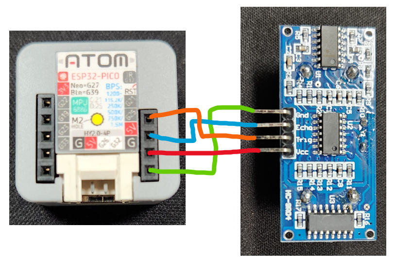
Wiring is very easy. Connect your wiring as follows.
- Atom Ground to HC-SR04 Ground
- Atom 5V to HC-SR04 Vcc
- Atom Pin G25 to HC-SR04 Echo
- Atom Pin G21 to HC-SR04 Trig
We will need to program the Atom Matrix to interact with the sensor and change the color of the entire screen based on the thresholds that are set. For that, we are going to make it easy by coding visually. This is where Visuino comes in handy.
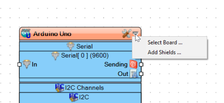
When you open a new project in Visuino you will be presented with the default board. For our project we need to select the M5 Stack Atom Matrix board by clicking the down arrow and clicking select board.
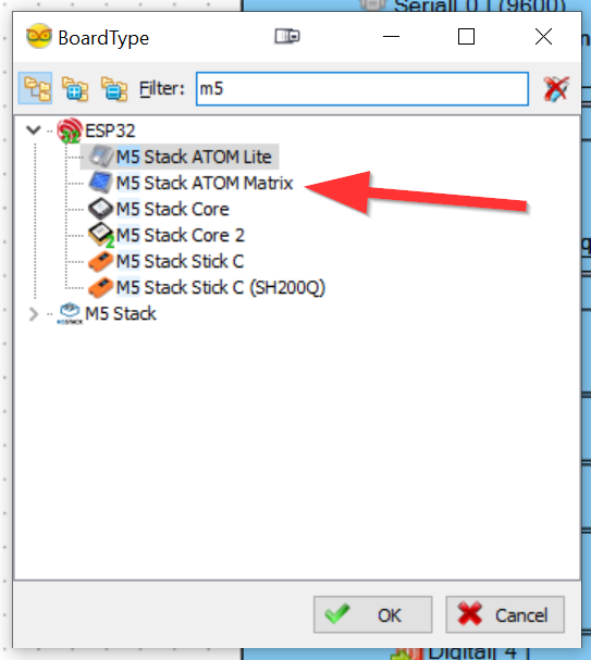
In the BoardType dialog, select the M5 Stack Atom Matrix board and click OK. After that, you should see the correct board type at the top of the board window.
We will need to add some additional components to the palette so that we can work with them. In the right-hand column, search for and add the following (you might see more than one option for the same thing – double-click only one to add to the palette):
- Ultrasonic Ranger
- Compare Analog Value
- Detect Edge
- Color Value
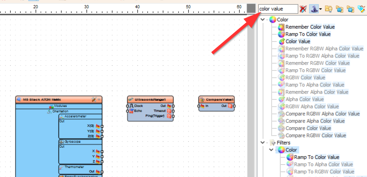
Also, note that my sidebar has small icons. If you are first running Visuino, you might have large icons or something slightly different than what I show here. The important thing is to look at the name and select by name.
Now that you have all the components, we will need to configure them and then attach everything together. If you get confused by this part, no problem, just watch my video and it will help you understand.
Let's start with the board itself. Select the board in the main window and it will show options in the left-hand pane. Select the three dots under the RGB Matrix section.
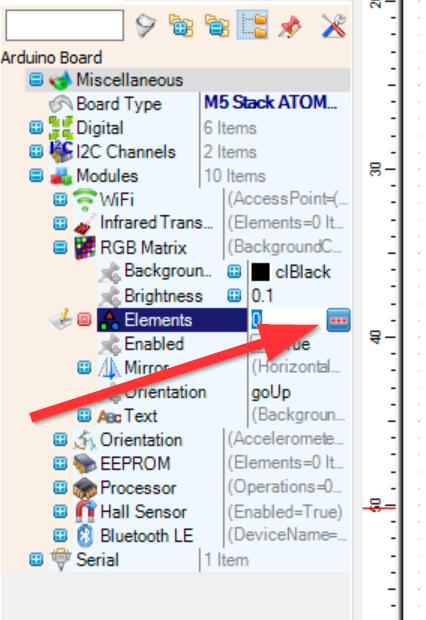
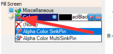
In the popup, drag Fill Screen to the left side and properties will appear in the main left window as it did for the main board. Click the pin next to Color and choose Alpha Color SinkPin. That is all we need there so you can close the Elements window.
Next, we will set the Compare Type to "ctBigger" in the Compare Analog Value component. Select the component in the main window and the properties appear in the left window just like all other elements.
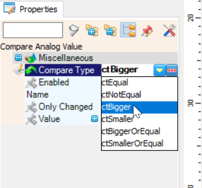
We also need to set the value to something that will trigger the color change based on that value. In my testing, that value is in cm so if you want to trigger the color change at 30cm, put 30 in that value. You can experiment with this later to get it just right. For my car in the garage example, I am going to want ~76cm. The sensor is supposed to measure up to 400cm in perfect conditions. Ok, all done with that one.
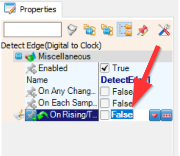
Let's move on to the Detect Edge component. For this one, we are going to set the "On Rising/True" property to False.
Finally, let's configure the Color Value component.
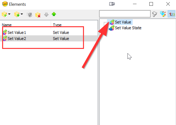
Double-click the component to bring up the Elements. We are going to add two colors, Red and Green. In the Elements window, double-click the "Set Value" two times to put two Set Value options on the left side.
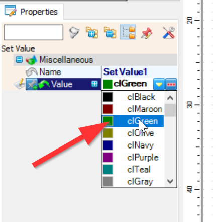
Click each of the values, one at a time, and choose "clRed" and "clGreen" under the Miscellaneous properties in the left-hand side of the main window. It doesn't matter what colors you choose as long as they are different. These colors will display on the full screen of the Matrix and will change depending on the trigger status in the ultrasonic sensor.
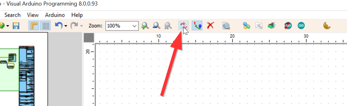
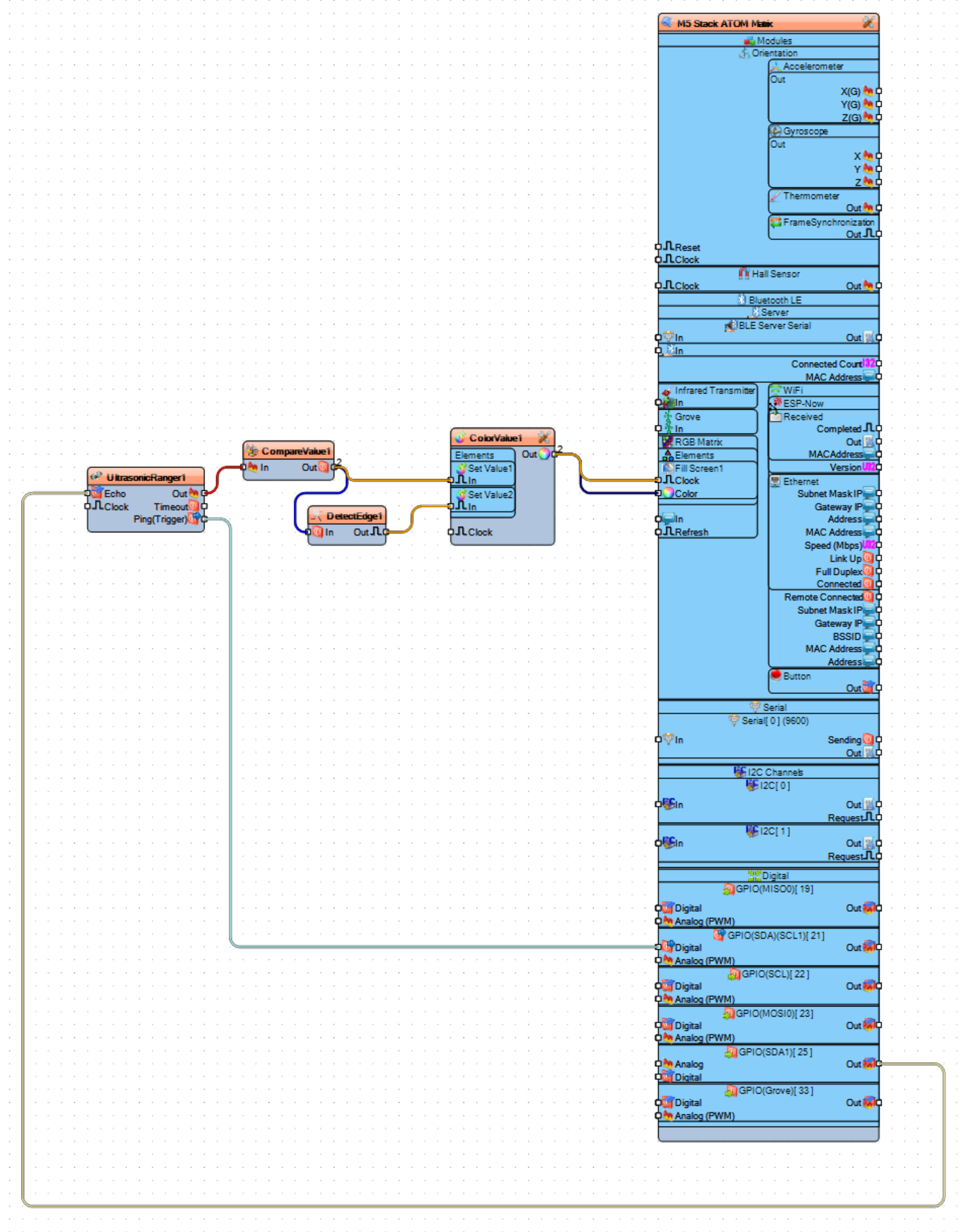
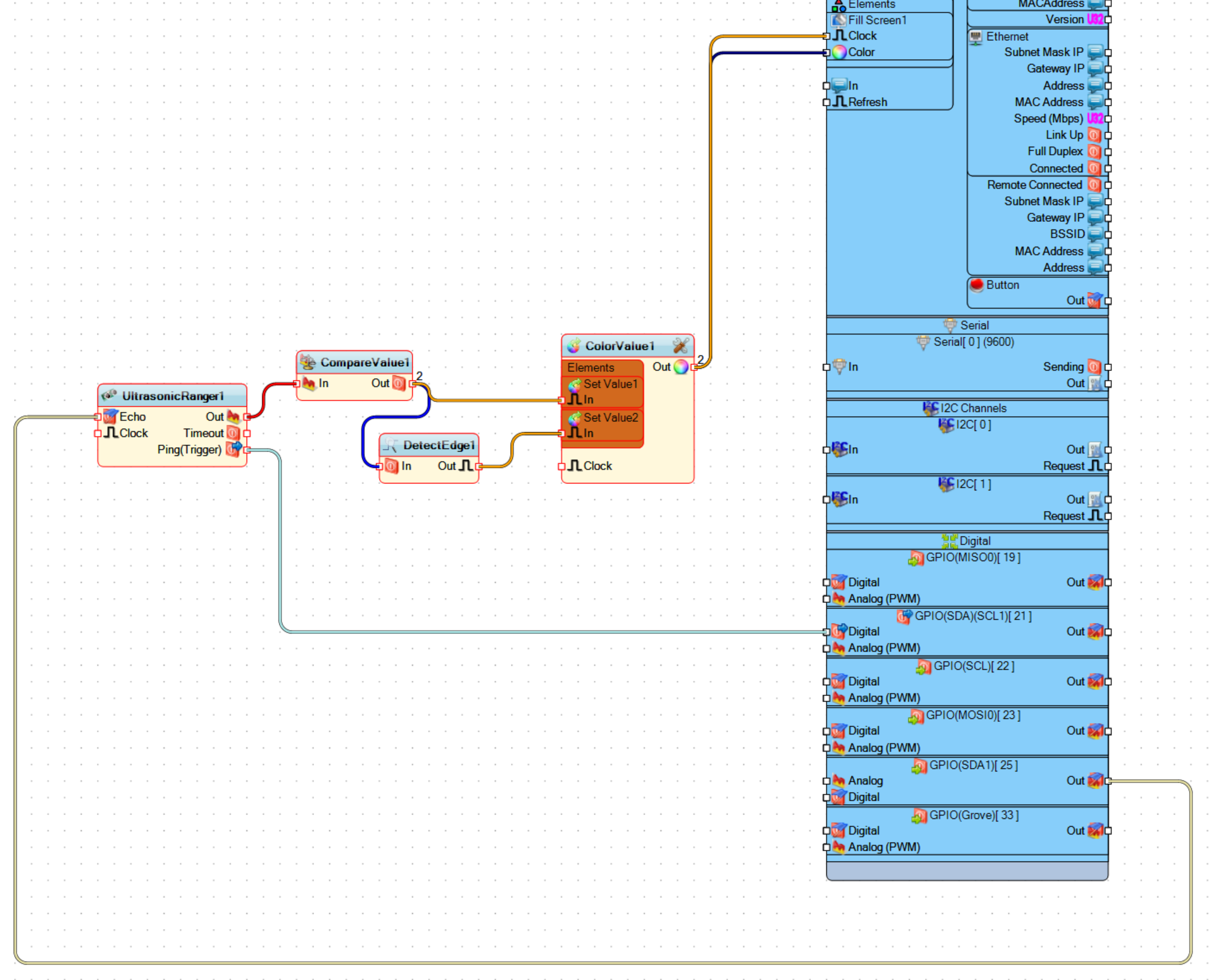
Now it's time to connect all the pieces. For this, we will just drag connectors between all the components in the appropriate places. Click on the square on one connector and drag to the other connector (see the video if I've confused you). The nice thing is that once you connect the two points, Visuino will make a nice line for you between the two. If you want it to be pretty, you can tell Visuino to Auto Arrange all the components. I have mixed results with this so use it with caution if you have spent a good deal of time moving things around.
When you are all done, you should have connections that look like this.
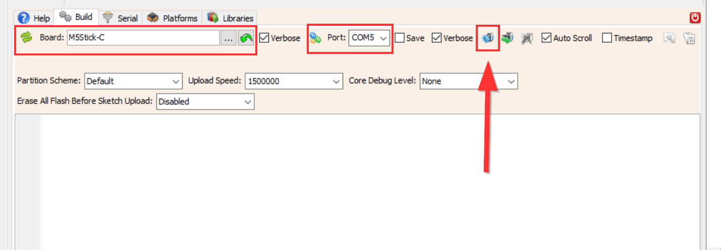
Now that all the "programming" is done, it is time to compile and install it on the Matrix. At the bottom of the Visuino window is a series of tabs. If you don't see the tabs, click the red power-looking button at the very bottom of the window.
Choose the "Build" tab. Select M5Stick-C Board type, and the COM port your device shows up as (I assume you plugged it into your PC already). Click the "Compile/Build and Upload" button and cross your fingers!
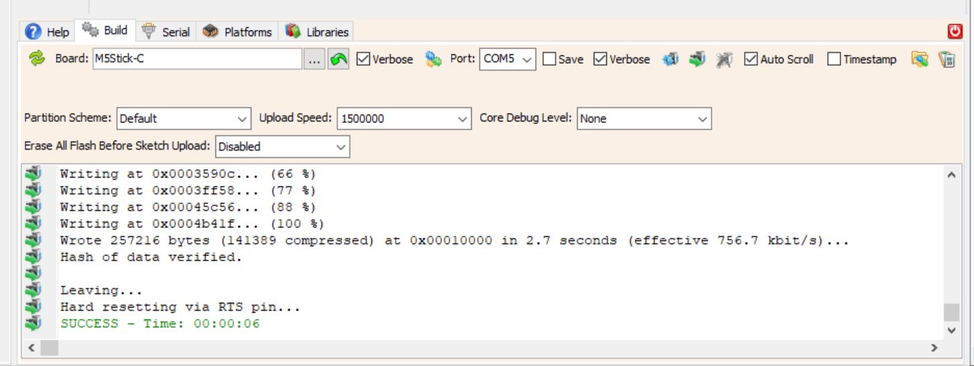
If all went well, you'll see the "SUCCESS - Time: nn:nn:nn" message at the bottom of the compile window.
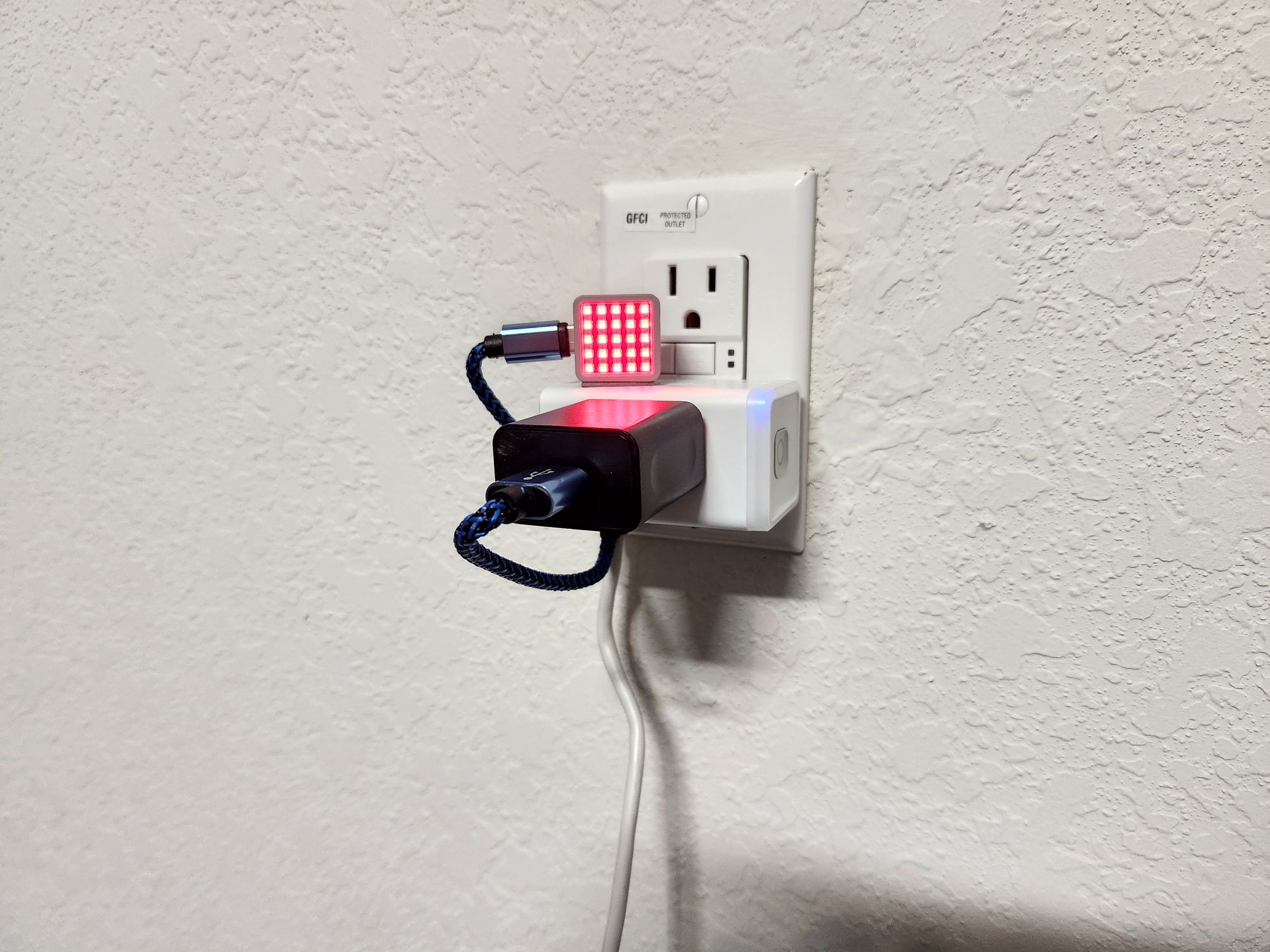
Once you have compiled everything, hook up the wiring if you haven't already done so and test. The color of the matrix should change as you put something in front of the transducer. Experiment with how far out you can move an object from the sensor to see when it triggers or un-triggers. In the video, I show a very brief view of the car pulling into the garage and the sensor causing the Matrix to change colors.
The final (so far) placement of the Matrix so that it can be seen over the dashboard of the car.
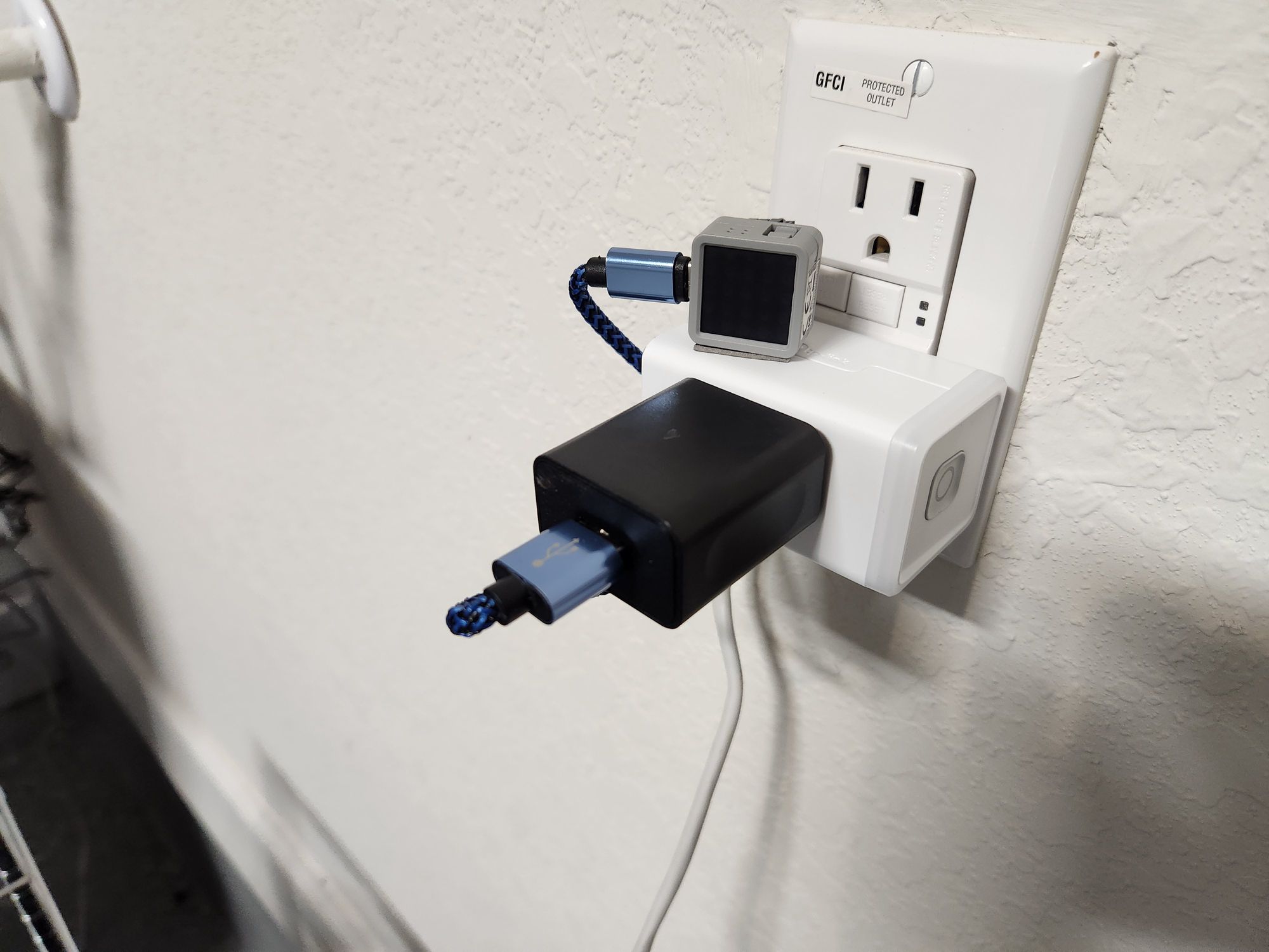
You can see that I also added a smart plug that turns on the Matrix and sensor for 5 minutes only when the garage door is open. This saves wear and tear on the display and sensor and hopefully prolongs their lifespan.
Every mounting situation will be different and I can 100 percent guarantee that there are better ways to mount this whole setup. I'll leave it to you to figure that part out.